This post is aimed at beginners, so experienced engineers can probably ignore it and move on.

HDL languages like VHDL and Verilog are not like normal programming languages; instead of executing line 1, then line 2, then line 3, and so-on, you have many lines executing at once (sort of).
HDL code is also somewhat unique in that you need to have two different headspaces when reading/writing it:
- One headspace for writing testbenches (like traditional software; do whatever you want)
- One headspace for code that ends up in the chip (which uses fewer language features and is more strict)
I’m going to be focussing on the second style of coding.
Structure Of A VHDL File
A VHDL file starts with some library import statements, followed by 2 main parts: the entity and the architecture.
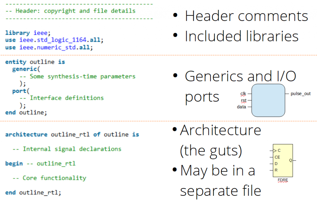
The entity section is where you define the I/O pins of your module (or the pins of the chip, if it’s describing your top-level). It’s made up of one or two parts: generics and ports.
- The
genericsection is where you describe parameters that get locked down once the design is synthesised. If you want to describe a data bus that is ‘n’ bits wide, then you can define what ‘n’ is in this section, then refer to it in the port section below. If your module is used in a hierarchical design, then each instance of this module can have different values (if you like). - The
portsection is where you describe the wires and busses that go in and out of your module.
The bottom part of the file is the architecture and it is where you describe the functionality of your design. It has 2 sections: declarations and core functionality.
- Between the
architectureandbeginstatements, you can define signals, constants, types, records and all the other things that will be used in the next part. - Finally, between the
beginandendstatements, you describe what your core functionality is actually doing.
Reading VHDL Code
What I want to do is show you how to look at a piece of VHDL code and imagine what it will turn into once it has been synthesised into your target FPGA. This is a key FPGA design skill because you can make more efficient designs if you know what your code will turn into.
The example below shows a basic PRBS generator. Its job is to generate a random-looking sequence of 0’s and 1’s with 1 new bit output every clock cycle (see Xilinx XAPP210 for more on PRBS):
library ieee;
use ieee.std_logic_1164.all;

entity prbs7_gen_1bit is
  port(
    -- Clock, Reset and Enable signals
    clk  : in std_logic;
    rst  : in std_logic;
    i_en : in std_logic;                 -- '1' = Enabled

    o_prbs7 : out std_logic
    );
end prbs7_gen_1bit;

architecture prbs7_gen_1bit_rtl of prbs7_gen_1bit is

  signal sreg : std_logic_vector(6 downto 0);

begin  -- prbs7_gen_1bit
----------------------------------------------------------------------
-- Description:
--  Generate a PRBS7 data stream
  process (clk, rst)
  begin
    if (rst = '1') then
      o_prbs7 <= '0';
      sreg    <= (others => '1');

    elsif (rising_edge(clk) = '1') then
      if (i_en = '1') then

        if (sreg = "0000000") then
          -- Prevent an all '0's pattern from locking up the generator
          sreg <= (others => '1');
        else
          -- Generate the next bit in the stream
          sreg <= sreg(5 downto 0) & (sreg(6) xor sreg(5));
        end if;
        o_prbs7 <= not sreg(6);

      end if;  -- Enabled
    end if;
  end process;

end prbs7_gen_1bit_rtl;
The entity name is prbs7_gen_1bit and (with luck), it’s the same as the VHDL file name.
Q: Why do people use the same name for the file and the entity?
A: Because it makes it easier to find the code once your module is buried deep inside a design hierarchy.
In this example, the architecture name is prbs7_gen_1bit_rtl. My naming convention is optional; some examples are “_rtl” or “_arch” or “_beh“. If you see someone has used one of these suffixes, they often mean:
- “
rtl” = functional code - “
arch” = an architectural module, stitching sub-modules together with no real functionality of its own - “
beh” = a behavioural model for simulation; not intended for synthesis
Key Skill: Synthesise Code In Your Head
Being able to do this makes you a better HDL coder. I’m going to show you how to think in terms of the physical hardware blocks, not software functions like “if”, “class”, “procedure”, etc.
If you look through the code for the keyword “process“, you’ll see that there’s one which has (clk, rst) after it. The signals in brackets are called the “sensitivity list” and nothing happens in the process until any of those signals change. This process has a clock, so it’s called a “clocked process”.
Note: “rst” is also on the sensitivity list; this means that the process has an asynchronous reset.
Focus only on the clocked process. I’ve repeated just that section of the code below and highlighted every line which is doing an assignment in the “clocked” section. You’re looking for any line with the “<=” assignment operator in the clocked part of the process, starting from the “rising_edge(clk)” line (not the 2 lines in the reset part at the top):
  process (clk, rst)
  begin
    if (rst = '1') then
      o_prbs7 <= '0';
      sreg    <= (others => '1');

    elsif (rising_edge(clk) = '1') then
      if (i_en = '1') then

        if (sreg = "0000000") then
          -- Prevent an all '0's pattern from locking up the generator
          sreg <= (others => '1');
        else
          -- Generate the next bit in the stream
          sreg <= sreg(5 downto 0) & (sreg(6) xor sreg(5));
        end if;
        o_prbs7 <= not sreg(6);

      end if;  -- Enabled
    end if;
  end process;
Count the number of bits involved in every signal to the left of the “<=” assignment operator. In this case, we have 7 bits for the “sreg” because std_logic_vector(6 downto 0) is 7 bits, and 1 bit for the output “o_prbs7“. I expect to see a total of 8 flip-flops in the finished design, looking something like this.
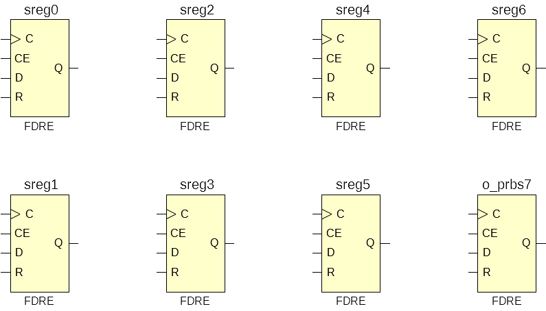
Being able to do this is key to estimating the overall size of any design that you’re thinking of making.
Next, look at what affects each clocked thing.
- What affects “
o_prbs7” ?- Everything to the right of the “
<=” assignment operator and any conditions that were involved in getting there. - “
sreg(6)“, “i_en“, “clk“, “rst“
- Everything to the right of the “
- What affects “
sreg(6)“?- “
sreg(5)“, “i_en“, “clk“, “rst“
- “
- etc.
- What affects “
sreg(0)“?- “
sreg(6)“, “sreg(5)“, “i_en“, “clk“, “rst“
- “
Any logical operations will require a lookup-table (LUT) to make the functionality that you want. In this example, there’s two: an XOR and a NOT.
So, I expect to see something like this:
I synthesised this little block of code in Vivado, then I took a screenshot of the result:
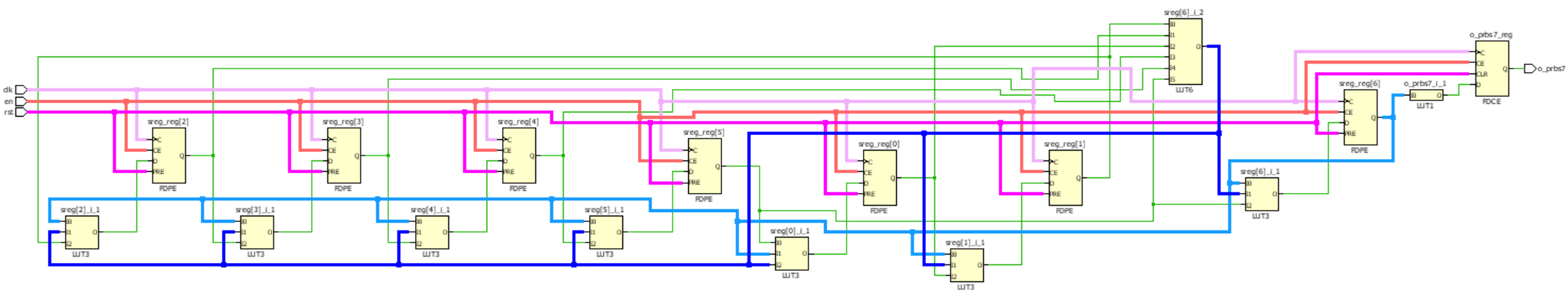
Oops, I forgot the line which checks if the shift-register is stuck at all-zeros: “if (sreg = ”0000000”) then“. This got turned into the 6-input LUT at the top with the dark-blue output. I got the right number of flip-flops, though.